Data center networking made easy
Recently, one of our customers came to us with the following proposition:
We just upgraded our data center and we need someone to help us configure stable, fast and scalable networking. Can you guys help us with a BGP-EVPN VXLAN Spine-Leaf fabric?
The answer, of course, was yes.
In this article I will guide you on how to configure your own similar architecture. But before that, let’s quickly go over what all of this means and why somebody would be interested in such a thing to start with.
Spine-Leaf fabric
A Spine-Leaf fabric is a datacenter networking architecture which contains two types of switching layers, spines and … who would’ve guessed, leaves.

- Leaf switches consist of access switches that aggregate traffic from the datacenter servers and are directly connected to the spine switches.
- Spine switches’ role is to connect all of the leaf switches creating a full mesh, ensuring connectivity between all datacenter servers.
A spine leaf architecture greatly reduces the number of hops between servers as opposed to a classic network architecture, servers being essentially 2 leaves (or 4, if we're talking about a 3 tiered spine-leaf architecture) and one spine away, but as you can see, an increasing number of spines and leaves also greatly increases the number of connections in the mesh, so this architecture usually becomes limited by the hardware used.
Cabling a spine-leaf architecture can also become a nightmare of its own, but again, different customer needs lead to different solutions.
BGP-EVPN VXLAN
BGP (Border Gateway Protocol) is a protocol that enables the internet to exchange routing information between Autonomous Systems (AS). An Autonomous System is a collection of networks regulated by the same organization. In essence, an AS is an abstraction of multiple networks into a single entity, greatly facilitating routing.

VXLAN (Virtual eXtensible LAN) is a MAC-in-UDP encapsulation protocol that addresses the inherent limitations imposed by VLANS, extending layer 2 connectivity by running as an overlay on top of existing layer 3 networks.

Despite being really useful, the problem with VXLAN is that it doesn’t provide any optimal switching and routing functionality because, like usual layer 2 protocols, it is based on a “flood and learn” mechanism.
To combat this limitation, VXLAN is paired with EVPN. EVPN is an extension to BGP that allows it to transport Layer 2 MAC and Layer 3 IP information. The combination of VXLAN and EVPN is known as a BGP EVPN VXLAN fabric.
EVPN acts as the control plane of the fabric (controls how data is routed), while VXLAN represents the data plane (contains the actual means of routing the data and does the routing).
Why?
Why would a company choose a BGP EVPN VXLAN fabric when upgrading their network architecture? Well because it provides a bunch of benefits:
- Speed: inherent to the spine leaf architecture
- Scalability: VXLAN not only extends VLANs over layer 3 networks by providing encapsulation, but it also allows for more layer 2 networks (up to 16 million, up from the 4096 available with VLAN)
- Flexibility: servers can be placed anywhere as traffic separation is done through network segmentation using VXLAN segment IDs or VXLAN Network Identifiers (VNIs)
- Multi-tenancy: Supports multi-tenancy by allowing different tenants to have their own isolated logical networks within the same physical infrastructure
- Security: Provides tenant isolation using VXLAN Network Identifiers (VNIs), preventing unauthorized access between tenants
- Operational Simplification: Combines Layer 2 and Layer 3 services into a single control plane (BGP), simplifying network operations and management
Now lets move onto the actual implementation of a BGP EVPN VXLAN fabric:
Tutorial
Contents:
- Prerequisites
- Configure general settings
- Configure underlay IP addressing
- Configure OSPF Underlay Routing
- Configure Underlay PIM Multicast Routing
- Configure BGP EVPN Adjacencies
- Prepare NVE Interfaces
- Configure Tenant VRF_A
- Leaf-2 Reconfiguration
- VRF Leaking
Prerequisites:
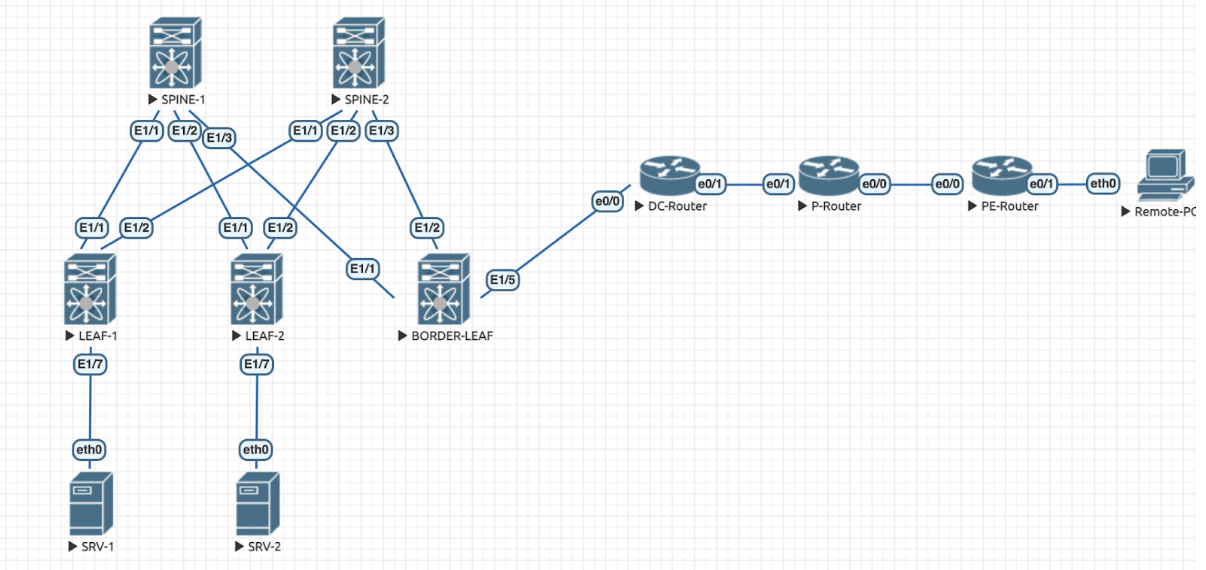
- Either a physical or virtual environment of a spine leaf topology. We will use the virtual environment below in this article but you can adapt the configuration to fit your specific needs:
- The ability to not break down crying after trying to fix something for an entire day just to realize it was a typo all along
Configure general settings
In this step we’re just making sure that we set the correct hostname for each device to allow for easier identification and also that we are activating all of the features we will use in the next steps.:
- Configure hostname
- Configure features required
- feature privilege
- nv overlay evpn
- feature bgp
- feature pim
- feature ospf
- feature nv overlay
- feature vn-segment-vlan-based (leaf only)
- feature interface-vlan (leaf only)
hostname LEAF-1
feature privilege
nv overlay evpn
feature ospf
feature bgp
feature pim
feature interface-vlan
feature vn-segment-vlan-based
feature nv overlay
Configure underlay IP addressing
Pretty straight forward, just configure the IP’s on the devices. I used the tables below, your IP’s might vary:
interface Ethernet1/1
  no switchport
  ip address 10.0.11.2/30
  no shutdown
!
interface loopback0
  ip address 100.100.100.3/32
!
We should now be able to check the connectivity on the /30 links. Do not check it on the loopbacks, it will not work.
ping 10.0.11.1Configure OSPF underlay routing
Next, lets enable OSPF underlay routing:
1. Activate OSPF with Process Name “LAB”
Enable OSPF with the process name "LAB" to initiate OSPF configuration:
router ospf LAB
2. Configure Loopback0 IP Address as Router ID
Set the OSPF Router ID using the IP address of Loopback0 for each node:
router-id <lo0_ip_address>
3. Activate OSPF on Configured Links and Loopback Interfaces in Area 0
Enable OSPF on Ethernet1/1 interface and Loopback0 interface, placing them in OSPF Area 0:
interface Ethernet1/1
  ip router ospf LAB area 0.0.0.0
!
interface loopback0
  ip router ospf LAB area 0.0.0.0
4. Configure OSPF Process to Log Adjacency Changes
Enable OSPF to log adjacency changes for monitoring and troubleshooting purposes:
log-adjacency-changes
5. Turn on Logging Level 7 on the Console
Set the logging level to 7 for OSPF-related messages on the console:
logging console 76. Check OSPF Adjacencies
To verify OSPF neighbor relationships, you can use the following command:
show ip ospf neighborThis command will display the OSPF neighbors, their states, and other relevant information.
Ensure that OSPF adjacencies are established among the configured nodes and interfaces. If there are issues, you can refer to the logs and adjacency changes for troubleshooting.
Your configuration should look something like this:
router ospf LAB
  router-id 100.100.100.3
  log-adjacency-changes
!
interface Ethernet1/1
  ip router ospf LAB area 0.0.0.0
!
interface loopback0
  ip router ospf LAB area 0.0.0.0
!
logging console 7
!
Configure underlay PIM multicast routing
To enable PIM multicast routing follow the configurations below on the spines and leaves:
Configuration on Spines:
ip pim rp-address 100.100.100.254 group-list 239.0.0.0/16
ip pim ssm range 232.0.0.0/8
ip pim anycast-rp 100.100.100.254 100.100.100.1
ip pim anycast-rp 100.100.100.254 100.100.100.2
interface loopback0
  ip pim sparse-mode
!
interface Ethernet1/1
  ip pim sparse-mode
!
Configuration on leaves:
ip pim rp-address 100.100.100.254 group-list 239.0.0.0/16
ip pim ssm range 232.0.0.0/8
interface loopback0
  ip pim sparse-mode
!
interface Ethernet1/1
  ip pim sparse-mode
!
To verify PIM adjacencies and multicast routes, you can use the following commands:
show ip pim neighborPrint PIM neighbors
show ip mrouteDisplay the multicast routing table
Configure BGP EVPN adjacencies
We will continue by configuring the BGP EVPN adjacencies:
Configuration on the spines:
router bgp 65500
  router-id 100.100.100.1
  log-neighbor-changes
  neighbor 100.100.100.3
    remote-as 65500
    update-source loopback0
    address-family l2vpn evpn
      send-community
      send-community extended
      route-reflector-client
  neighbor 100.100.100.4
    remote-as 65500
    update-source loopback0
    address-family l2vpn evpn
      send-community
      send-community extended
      route-reflector-client
  neighbor 100.100.100.5
    remote-as 65500
    update-source loopback0
    address-family l2vpn evpn
      send-community
      send-community extended
      route-reflector-client
Configuration on the leaves:
router bgp 65500
  router-id 100.100.100.3
  log-neighbor-changes
  address-family l2vpn evpn
    advertise-pip
  neighbor 100.100.100.1
    remote-as 65500
    update-source loopback0
    address-family l2vpn evpn
      send-community
      send-community extended
  neighbor 100.100.100.2
    remote-as 65500
    update-source loopback0
    address-family l2vpn evpn
      send-community
      send-community extended
To verify the BGP EVPN adjacencies, you can use the following command:
show bgp l2vpn evpn summaryDisplay a summary of BGP EVPN peers and their states
Prepare NVE interfaces
We will now prepare the NVE interfaces, configured only on the LEAVES, using Loopback1 as a source interface. Additionally, we need to use EVPN as the signaling protocol and we will configure the global fabric anycast gateway with MAC address "dead.beef.0100":
interface nve1
  no shutdown
  host-reachability protocol bgp
  advertise virtual-rmac
  source-interface loopback1
!
fabric forwarding anycast-gateway-mac dead.beef.0100
To verify the NVE interface configuration, you can use the following commands:
show interface nve 1Display the detailed configuration and status of NVE interface 1
show nve interface nve 1
Display specific information about NVE interface 1, including its status, source interface, and any associated configurations
Ensure that the NVE interface is up and configured correctly. Verify that it is using Loopback1 as the source interface and that the global fabric anycast gateway MAC address is set to "dead.beef.0100".
Configure VRF_A
Now, let’s set up VRF_A on LEAF-1 and LEAF-2, enabling communication between servers SRV-1 and SRV-2:
VRF_A Configuration
VRF_A is created with a unique VNI (10100) and route distinguisher (auto-generated). It facilitates communication within the VRF.
- L3VNI Configuration (VLAN 100): Interface VLAN 100 is associated with VRF_A, allowing IP routing within the VRF.
- L3VNI VLAN Configuration (VLAN 100): VLAN 100 is associated with L3VNI, providing Layer 3 connectivity for VRF_A.
- L2VNI Configuration (VLAN 500): Interface VLAN 500 is placed within VRF_A, ensuring Layer 2 connectivity within the VRF.
- Access Interface (Ethernet1/7): Ethernet1/7 is configured as an access port in VLAN 500, allowing devices in VLAN 500 to communicate.
The final configuration should look something like this:
vrf context VRF_A
  vni 10100
  rd auto
  address-family ipv4 unicast
    route-target import 65500:100
    route-target import 65500:100 evpn
    route-target export 65500:100
    route-target export 65500:100 evpn
interface Vlan100
  description L3VNI VRF_A
  no shutdown
  mtu 9216
  vrf member VRF_A
  no ip redirects
  ip forward
  ipv6 address use-link-local-only
  no ipv6 redirects

vlan 100
  name L3VNI_VRF_A
  vn-segment 10100

route-map permit-all permit 10

router bgp 65500
  vrf VRF_A
    address-family ipv4 unicast
      redistribute direct route-map permit-all

interface Vlan500
  description LEAF-1 LAN 1
  no shutdown
  mtu 9100
  vrf member VRF_A
  no ip redirects
  ip address 192.168.1.1/24
  no ipv6 redirects
  fabric forwarding mode anycast-gateway

vlan 500
  name VLAN_500
  vn-segment 30500

evpn
  vni 30500 l2
    rd auto
    route-target import auto
    route-target export auto

interface nve1
  member vni 10100 associate-vrf
  member vni 30500
    mcast-group 239.0.0.1

interface Ethernet1/7
  switchport access vlan 500
To check that everything works we can use the following commands:
show nve peers
show nve vni
show ip route vrf VRF_A
show bgp l2vpn evpn vni-id 30500
LEAF-2 reconfiguration
Let’s now reconfigure Leaf-2 with VRF_B, maintaining the existing VRF_A configuration and enabling communication between servers SRV-1 and SRV-2 within their respective VRFs:
VRF_B Configuration
VRF_B is created with a unique VNI (10200) and route distinguisher (auto-generated). It facilitates communication within the VRF.
- L3VNI Configuration (VLAN 200): Interface VLAN 200 is associated with VRF_B, allowing IP routing within the VRF.
- L3VNI VLAN Configuration (VLAN 200): VLAN 200 is associated with L3VNI for VRF_B, providing Layer 3 connectivity within the VRF.
- L2VNI Configuration (VLAN 600): Interface VLAN600 is placed within VRF_B, ensuring Layer 2 connectivity within the VRF.
- Access Interface (Ethernet1/7): Ethernet1/7 is reconfigured as an access port in VLAN 600, allowing devices in VLAN 600 to communicate.
vrf context VRF_B
  vni 10200
  rd auto
  address-family ipv4 unicast
    route-target import 65500:200
    route-target import 65500:200 evpn
    route-target export 65500:200
    route-target export 65500:200 evpn
interface Vlan200
  description L3VNI VRF_B
  no shutdown
  mtu 9216
  vrf member VRF_B
  no ip redirects
  ip forward
  ipv6 address use-link-local-only
  no ipv6 redirects

vlan 200
  name L3VNI_VRF_B
  vn-segment 10200

route-map permit-all permit 10

router bgp 65500
  vrf VRF_B
    address-family ipv4 unicast
      redistribute direct route-map permit-all

interface Vlan600
  description LEAF-1 LAN 2
  no shutdown
  mtu 9100
  vrf member VRF_B
  no ip redirects
  ip address 192.168.2.1/24
  no ipv6 redirects
  fabric forwarding mode anycast-gateway

vlan 600
  name VLAN_600
  vn-segment 30600

evpn
  vni 30600 l2
    rd auto
    route-target import auto
    route-target export auto

interface nve1
  member vni 10200 associate-vrf
  member vni 30600
    mcast-group 239.0.0.2

interface Ethernet1/7
  switchport access vlan 600
VRF leaking
We can now enable communication between VRF_A and VRF_B by configuring VRF leaking. Ensure that VRF_A and VRF_B configurations below are present on both LEAF-1 and LEAF-2.
VRF leaking is established between VRF_A and VRF_B. RT-I/E (Route Target Import/Export) 65500:999 is used for leaking routes between the VRFs.
vrf context VRF_A
  address-family ipv4 unicast
    route-target import 65500:999
    route-target import 65500:999 evpn
    route-target export 65500:999
    route-target export 65500:999 evpn
!
VRF_A
vrf context VRF_B
  address-family ipv4 unicast
    route-target import 65500:999
    route-target import 65500:999 evpn
    route-target export 65500:999
    route-target export 65500:999 evpn
!
VRF_B
External connectivity for VRF_A
Let’s now establish external connectivity for VRF_A by configuring a subinterface on Ethernet1/5 with IP address 172.16.99.1/30 in VRF_A. We’ll set up an E-BGP session with IP address 172.16.99.2 in VRF_A with ASN 100:
interface Ethernet1/5
  no switchport
  no shutdown

interface Ethernet1/5.100
  encapsulation dot1q 100
  vrf member VRF_A
  ip address 172.16.99.1/30
  no shutdown

router bgp 65500
  vrf VRF_A
    address-family ipv4 unicast
      redistribute direct route-map permit-all
    neighbor 172.16.99.2
      remote-as 100
      address-family ipv4 unicast
!
What now?
Well, if you are asking yourself this you should know that you just configured your very own BGP-EVPN-VXLAN spine leaf fabric topology (a lot of keywords, I know).

You can now do… data center stuff with it, I suppose, like, configure multiple tenants and… sending packets and… other networky stuff. All jokes aside, this stuff is the backbone of modern cloud infrastructures and well, you just got to configure your own so congrats!